DISCLAIMER

All rights of photos and text reserved. Usage of photos or text from my blog on other websites or for any other purpose only with prior permission. If you want to use any material from my blog please contact me by email.

Wednesday, March 27, 2013

Low Cost Single Ended 6CB5A Amplifier - Part 4

Hi!

In the previous posts about these simple mono amplifiers, we already had a detailed look at the schematic, all the parts needed and the initial construction steps. The last post showed the mounting of all components which go directly to the metal plate and the wiring of mains and heater connections as well as the high voltage AC.


Now we will go through the remaining assembly steps. All the parts which are still missing will be soldered to terminal strips. First we have to make a foundation on which these can be attached. For this I used my famous aluminum profiles:


These two aluminium rails are supported on bolts which are attached to the plate by a screw through a hole:


Now the terminal strips can be screwed onto these rails. Before they get mounted they need to be prepared a bit. Some holes drilled in the right distance:


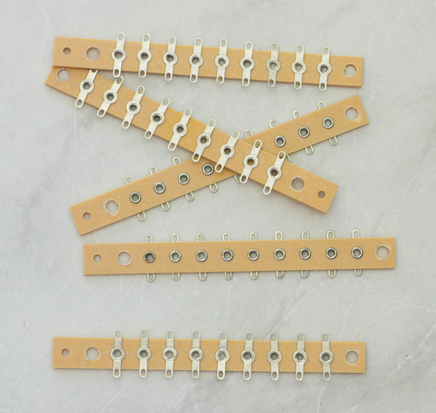
Parts will be mounted on two tiers. Three strips in the first one:


Two of them are closer to each other. These are for shorter parts and some parts will be mounted vertically on the left side. At this point it is already important to think about the layout of the ground. A ground bus scheme will be used, so it is a good idea to orient as many parts as possible such that their ground connections are on one side.

Let's start with the two silicon diodes which complete the rectifier bridge:


The andodes of the diodes will be at ground. The cathodes are connected to high voltage AC. They are hooked up to the plate terminals of the rectifier tube socket through a well isolated twisted pair. Their orientation indicates already that we want the ground bus to run along the terminal strip in the middle.

Now the two electrolytics which are wired in series for the first cap after the rectifier, are added along with their parallel resistors:


On the top of the left column the two 100 Ohm resistors are placed, which create the ground reference for the heater. Their ground side is oriented towards the centre. The left side is connected to the heater  of one of the signal tubes through a twisted pair of wires (blue wire). Since not much current is flowing through them, thin solid core wire can be used.

Now the second column gets populated with parts:


These are from the top: 1k cathode resistor of the 6N7 and it's bypass cap. Then the 500k grid to ground resistor of the output tube. Since I only had 1M parts in hand, two of them are connected in parallel. Below these the plate resistor of the driver 47k/20W. This dissipates a bit of power so we need a high wattage type. With this one we break the rule that all the solder lugs on the middle strip are for ground, since it connects to B+. We have to keep that in mind later on, when the ground bus is laid down. We need to jump over that. At the bottom the cathode resistor of the 6CB5A and it's bypass cap.

Now let's do the ground bus. For this we use a thick solid core copper wire. For example 1mm or thicker. First the insulation gets stripped off:


The insulation sleeve will be reused later. Don't throw it away. The bare copper wire is then bent into shape and soldered into the amp:


It runs all the way through the middle, jumping over the B+ connection of the 6N7 plate resistor and extends to the ground lift switch and ends at the minus pole of the speaker terminal. Another view from the side:


Now we add the connections to the signal tubes and some more of the missing parts:


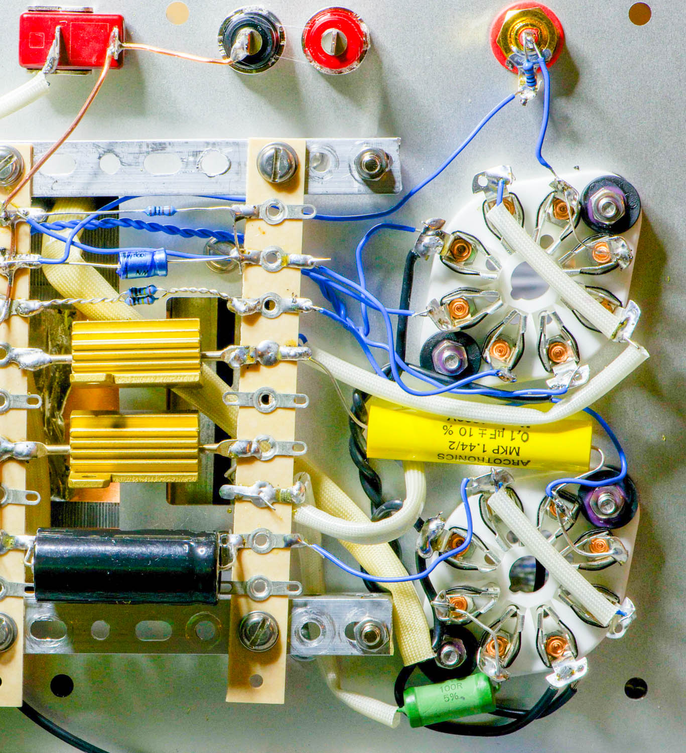
The 100k input resistor is soldered directly to the RCA socket. The coupling cap from driver to output tube (yellow MKP cap between the two sockets) goes directly to the grid pins of the 6CB5A socket and to the plate resistor on the other side. From there another connection is made to the plate pins of the 6N7. Since we have some high voltage there some extra insulation is applied. In the photo above also the connection from the cathodes to the terminal strip is already done as well as the ground connection to pin 1 of the 6N7 (this grounds the shell in case a metal tube is used). The green resistor on the bottom makes the connection from the 6CB5A screen to it's plate. This resistor should be soldered as close to the screen pin as possible. For the plate connection the third solder lug from the bottom on the rightmost terminal strip is used. There we also connect the wire to the plate cap of the 6CB5A which is already in place in the photo. It extends through a hole in the metal plate to the top of the tube.

Remember the insulation from the ground bus wire which we kept? This is used for the wire to the plate cap which we want to be very well insulated. Some of the thin solid core wire is pulled though that sleeve:


First a longer piece of the insulation of the thin solid core wire is removed. This way it can be easily pushed into the black sleeve. When it extends at the other end, the sire can be pulled through so that we have the insulated part inside the black sleeve:


For extra protection I pulled this through a piece of the white sleeve and soldered the plate cap on:


Only a few parts missing: The bank of 5 electrolytic caps which will be wired in parallel for the main B+ reservoir cap, choke and output transformer. For the caps we need more terminal strips. These are mounted on two more aluminum rails which are attached to the lower rails with bolts:


Before these got added, I already soldered some wires to the strips underneath for the connections to the remaining parts: ground, B+ from the rectifier and first cap and output tube plate. After the upper tier is completed it is difficult to reach these, so better add them before. 

Upper caps soldered in:


All connected in parallel, with two more pieces of the bare copper wire. This is how it looks from the side:


Now choke and output transformer get added and wired up:


Two more aluminium rails are used for this which again attach to the metal plate with bolts, long enough to keep them above the tube sockets. Extra insulation sleeves for the high voltage carrying wires.

Two more rails attached to the other ends of the choke and transformer. Another rail connecting these two for mechanical stability:


More bolts added which are needed to screw on the bottom lid, once the amp is inserted in the wooden frame.


Now everything is ready to be tested. After the test is complete the amp is put into the frame:


The bolts line up with holes in the bottom lid:


Through these everything is securely held in place by screws:


The bottom lid also carries the rubber feet on which the amp rests:


The finished amps:


Step by step testing and measurements will be covered in part 5. Stay tuned!

Best regards

Thomas

Sunday, March 24, 2013

MC step up transformer with selectable gain

Hi!

Often people use different cartridges with very different output voltages and impedances. For such situations it is desirable to have a MC step up transformer which can be adapted by switching between different step up ratios.


This is easily doable with transformers with split windings. Lundahl winds all his transformers with dual coils, so both the primary and secondary are composed of two individual windings. The datasheet of the LL1943 suggests two ratios which can be achieved by either wiring the primaries in parallel or in series. Thus allowing either a 1:16 or 1:32 step up ratio.

This can be easily made selectable. All that is needed are two selector switches with 2 poles. One for each channel. Or a single 4 pole switch which would allow to switch two channels at once. The schematic below shows how this is done:


In the schematic the switches are in the position which puts the primaries in series. Thus this represents the lower step up ratio.

A minor drawback of his schematic is the fact that the connection between the two windings goes through two switch contacts in case of the serial position. The next schematic shows how to avoid this:


It is quite easy to assemble such a MC step up. I will show this in a few photos. The RCA connectors, switch, ground connector and transformers are all wired on a metal plate which serves as the back panel:


The second schematic is a bit more difficult to wire but doable. The photo below shows the switch prepared for this:


I cushioned the MC transformers so that the mu metal casing doesn't get bent which would impact it's permeability. A close up showing the mounting of the transformers:


The back panel completely wired up:


A close up showing the wiring to the output jacks:


And a close up of one of the switches at the input side:


Now everything can be assembled into a wooden housing. The front panel holds the bolts to which the back is attached later on. It also gives some weight to the transformer, so it is not too easily pulled from the rack by interconnects:


The finished MC step up:


The back panel:


Best regards

Thomas

Thursday, March 21, 2013

Tube of the Month : The 6J5

Hi!

Today we will have a close look at an indirectly heated medium mu triode, the metal type 6J5 and it's glass equivalents 6J5G and 6J5GT.


The electrical characteristics of the 6J5 are identical to the ubiquitous 6SN7. It only contains a single triode instead of two as in the 6SN7. The 6SN7 is very popular among amplifier builders and also found it's way into many commercial designs. There are good reasons for it's popularity. It is very linear and has a decently low plate resistance making it suitable as driver in power amps. Pretty much everybody who builds amplifiers at some point used or considered the 6SN7. Hence it got quite costly. Therefor it is surprising that the electrically identical 6J5 seems not to be very popular and is still available at low prices.

The 6J5 uses an octal base. The pinout is pictured on the left. It has an amplification factor of 20 which classifies it as medium mu triode. The plate resistance is about 7kOhm which makes this tube usable with transformer coupling. Of course it is equally well usable LC or RC coupled or as a cathode follower. It is very often used in the famous and once popular SRPP and mu-follower circuits. The complete datasheet can be found here. Although it is a very nice tube, I rarely find it to match my needs. As a driver tube in a power amp it has just too little gain for a 2 stage design. Using two of them  cascaded (or two halves of a 6SN7) provides way too much gain. That's why I prefer tubes like 6N7 as drivers for small output tubes. For large output tubes like 300B or even 211 where the 6N7 has too high of a drive impedance, the 6J5 is not much better either. While still ok for a 300B maybe, I would not consider it for the large transmitting tubes.

Let's have a look at the plate curves. This is what the datasheet claims:


This looks very goo,d let's see how reality holds up to this. Here the curves of an actual 6J5GT tube taken with a curve tracer:


A fine tube, which deserves more use! That's why I will be using it in a stand alone phono preamplifier, which is based on the phono section of my Octal preamplifier. It will replace the 6N7 in that circuit for getting a lower output impedance to make that phono section usable stand alone.

There is another good use for the 6J5. In power amps which use both halves of the 6N7 paralleled, a 6J5 can be used without modifications. Compare the two pin outs:


The heaters are brought out on pins 2 and 7 on both of them. Both have the cathodes on pin 8. And since both are available as metal types, pin 1 is either connected to the metal shell or unused. In a socket wired for the 6N7, pins 4 and 5 would be connected together for the input signal. The 6J5 has the grid on pin 5 and pin 4 is unused. The plates of the 6N7 are on pins 3 and 6 which again would be tied together. The 6J5 has the plate on pin 3 and pin 6 is unused. Perfect! That means the 6J5 can drop into a socket wired for paralleled 6N7 without any changes. It would also bias up correctly in a circuit for the 6N7. It would only have less gain. This can be helpful in systems with too much gain (a common problem). I have recommended this substitute to users of amps from me which use the 6N7 as driver when they had a preamp with too much gain.

Now let's have a closer look at the different versions of 6J5s. Let's start with the metal shell variety:


And some close ups. This Sylvania has a nice shiny black:


The General Electric:


Two varaints of RCA:


The 6J5GT is a glass version, the GT stands for Glass Tube. Here a nice one from Dumont:


The plate structure:


Apparently they varied the construction over time. I have some with the getter applied at the top and some with the getter at the bottom of the tube:


Here a quite peculiar JAN 6J5WGT, made by Sylvania:


It has a nice brown micanol base:


But what's peculiar about this tube are the two plate structures inside as would be expected from a double triode: 


If you look closely, cathode and grid are only assembled inside one of the plates. It is better visible when the tube is lit up:


Obviously the same tooling and internal structure as for the 6SN7 was used, they kept the second plate inside for mechanical stability, but left the cathode and grid out.

Next a 6J5G in the 'coke bottle' or shoulder type (ST) shape:


Another view:


The plate structure:


The small fin on the to is attached to the rods which support the grid. It provides extra cooling for the grid.


Now, let's examine the internals of a 6J5, as has become a tradition of the Tube of the Month serious. Caution: If you are offended by photos showing the destruction of a vacuum tube, don't read any further.

Let's take one of the metal tubes, a General Electric:


The base can be easily taken off, when the metal is bent away in those spacings:


Slowly prying it open:


The base comes off:


The metal shell opens like a tuna can:


Part of the sealing is gone now:


Breaking the air tight shell. A first peek inside:


The electrodes are already visible:


Removing the triode from the metal shell:


The ring which held the getter:


The triode system:


Grid and cathode removed from the plate:


A close up:


Showing the scale of the grid spacing:


Another close up, the distance between the black lines is 1mm:


cathode removed from the grid:


The cathode and heater:


A close up:


That was all I have about the 6J5. I hope you enjoyed it. Stay tuned for the presentation of the phono stage circuit using this tube.

As a last one, a 6J5 with a panorama view:


Best regards

Thomas