DISCLAIMER

All rights of photos and text reserved. Usage of photos or text from my blog on other websites or for any other purpose only with prior permission. If you want to use any material from my blog please contact me by email.

Saturday, May 26, 2012

Tube of the Month: The EC8020 (revisited)

Hi!

Normally I present a different tube type in each article of the tube of the month series. But in case of some exceptional tubes it is worth revisiting them. In the recent months I could substantially increase my stock of Telefunken EC8020s. Which offers the opportunity to provide some interesting new photo material of my favorite indirectly heated tube.


All technical aspects and plate curves have already been discussed in last years article about this tube. Today I will mainly show more photos.


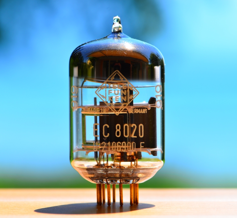
With my recent acquisitions of EC 8020 tubes I also got a very rare specimen, an early lab sample:


This must be a sample from the Telefunken development lab, when they worked on this tube type. This was probably meant as early samples to key customers to evaluate the new type.

The sticker says: "Confidential lab sample. No guarantee for the availability of more tubes and for the initially published technical data."


The internal structure is very similar to that of the regular EC8020s:


In my collection of EC8020 triodes there are also a few duds. This offers the opportunity to dissect one and show some close up photos of the internal details.

First the glass needs to be broken:


Removing the glass envelope gives a better view onto the construction of the electrodes:


The plate is composed of two extra large and thick pieces for good cooling. They need to be able to dissipate 8 Watts.

A peek between the two parts of the plate, showing the grid and cathode:


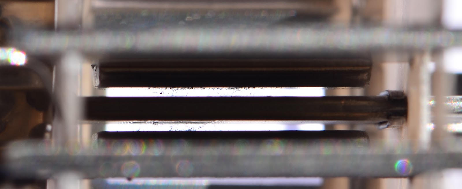
When the glass broke and air rushed in, this damaged the cathode surface and ripped some of the very fine grid wires as can be seen in this close up:


remarkable how delicate and fragile the grid wires are. We will see more of that further down.

More views of the internals:


The silvery 'cage' around the actual structures is there for mechanical stabilisation.


The major part of the plate extending to one side is only for cooling.


The small ring on the top held the getter material which is evaporated after evacuation of the air from the envelope. After the getter deposits like a mirror on the upper dome, the ring has no function anymore. Here a close up of the bottom part with the pins removed. This shows how the cage is clamped to the mica supports:


Slightly right to the middle the cathode sleeve can be seen with the heater wire extending out of it. Here a close up:


The heater is wound in a spiral and sprayed with some insulation material to provide isolation to the cathode.

Top mica supports and getter ring removed:


The next photo shows nicely that the majority of the plates is just for cooling. Only a small part is actually 'active' and has the right distance to the cathode and grid.


A close up showing the active part. The heater wire is removed from the cathode sleeve:


Next the two parts of the plate are removed:


Close up to cathode and grid:


The plates. The outsides are coated with graphite for better heat dissipation properties. One side on each plate is bent to create the exact distance to to grid and cathode:


Now a close up showing grid and cathode. This section got damaged when air rushed in after breaking the glass. Part of the cathode surface flaked off and ripped the grid wires.


In the next photo is done with a ruler to give an idea of the size:


The ruler is centimeter based. The distance between the short lines is 1mm. The next photo is zoomed in to show how thin those grid wires are and how close they are wound together:


About 20 grid wires over a distance of 1mm. That's about 50 micron between the grid wires. This is micro electronics from the early 1960ies!

The next photos show another comparison:


The large 'wire' in front of the grid is actually a human hair!

Here close up:


The diameter of the grid wire is less then a tenth of a human hair!

Another shot with a hair in comparison:


This tube is a truely stunning piece of engineering. Telefunken went to the limits of vacuum tube technology to achieve the unparalleled performance of this tube.

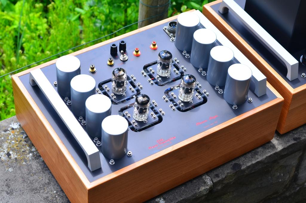
Here a peek at my stash of EC8020s:


I hope you enjoyed this second article about this tube. The EC8020 remains my favorite choice for LCR phonostages and similar small signal applications. I have plans for a fully differential LCR phonostage with this tube. Stay tuned for updates about that.

Best regards

Thomas


Wednesday, May 23, 2012

Cool Gales Audio Fest 2012

Hi!

Cool Gales will host it's annual audio fest this year on May 26. As last year it will take place in the Bath & County Club in Bath, UK.


Unfortunately, I will not be able to attend this year. But I sent a single ended 45 amplifier and a 6AH4 linestage.


This combo will be demoed with Aspara Acoustics speakers. Last year these speakers worked nicely with a 46 amp which is very similar to a 45. The frontend will be provided by Frank Schröder, who will bring an Artemis turntable with a strain gauge cartridge.

To bad I cannot make it to the show, I'm sure it will be as much fun as last year. And Bath is such a nice city, always worth a visit.


Best regards

Thomas

Sunday, May 20, 2012

The Modular Preamplifier, Part 10: 6AH4 Linestage

Hi!

The linestage version of the modular preamp sytsem with indirectly heated triode is finished.


It uses the 6AH4. Like all gain stages of the modular preamp it has it's own external power supply.


The circuit is exactly the same as the linestage section of the Octal preamplihier Mk2. The power supply uses the same full wave bridge with 4 6AX4 TV dampers and choke input filter. Only the heater supply is different. In the Octal preamp all heaters are supplied with DC, since it also contains a hum sensitive phono section. In a linestage it is sufficient to heat the tubes with AC. This simplifies the supply and works hum free. The heaters are just referenced to ground through two resistors across the heater line.


Here a photo which shows the inside construction of the preamp and power supply. The PSU is completed. The preamp still misses all the wiring from the inputs to the selector switch in this picture.


The linestage has 5 inputs. Four of them are regular inputs with 100kOhm input impedance for all kinds of line sources. One set of inputs goes through 1:4 step up transformers. These are reserved for low impedance sources which need some additional gain.


The two sets of output jacks are wired in parallel. Separate binding posts which connect to chassis and signal ground. A ground lift switch provides the option to either connect signal ground with chassis or have them disconnected. This allows for adjustment in case of ground loops in the system. The power supply is hooked up to the preamp trhough an umbilical with 5 pin Amphenol connectors.


The sound is the same as the linestage section of the Octal preamp Mk2. It uses the same AVC from intactaudio. Maybe a tad more refined since it has it's own dedicated power supply, which is shared with the phono section in The Octal preamp.


The next part of the modular preamp to be finished will be the linestage with the directly heated 10Y.


Best regards

Thomas

Sunday, May 13, 2012

Another E55L LCR phono preamplifier

Hi!

Here are some photos of a recently finished LCR phonostage with the E55L tube.


For those who don't want the six chassis of the modular preamp and who want to actually see the tubes, I have this more compact version which is in another style.


More compact as the six chassis version, but still a hefty preamp with external power supply:


The wooden frames are approximately 43 cm wide, 30cm deep and 12cm high. The frames are made of cherry wood.


The weight is quite hefty since it is loaded with iron. Two power transformers, seven (!) chokes, including a choke in the DC heater supply. Six signal transformers (excluding MC step up transformer). And the RIAA coils (In this case Tango EQ2L units.


This version was built on request. It is MM only, but MC transformers can be integrated. Gain is approximately 40dB. Depending on the selection of MC step up transformers, more than 70dB are achievable.


Sound is similar to my other LCR phono stages. The E55L is a good alternative to the EC8020 (which still remains my favorite). Very low noise and the E55L proofed to be very suitable in terms of microphonics. The mechanically damped mounting of the sockets helps of course.


Don't hesitate to contact me, if you are interested in such a preamp. It is also availabe as a kit. Kits can include all chassis material, but I can also provide partial kits if you want to build your own housings or if you have specific parts which you want to use in your preamp.

Best regards

Thomas